Contract Manufacturing for Injection Molded Plastic Products in North America
(800) 824.0607
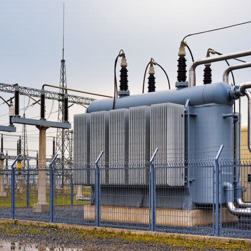
Substation Transformers are the quiet, heavy-duty machines behind reliable power delivery. They stand between high-voltage transmission lines and the lower-voltage networks serving factories, hospitals, offices, and homes. Inside a fenced substation, a transformer may weigh several tonnes, hum steadily, and operate through heat, rain, dust, and electrical faults.
Their purpose is practical. They raise or reduce alternating voltage while keeping the frequency unchanged. This process supports efficient transmission and safer distribution. Windings, a magnetic core, insulation, cooling equipment, bushings, and protective devices work together. If one part weakens, the entire power route can become vulnerable. Small details matter.
Power-transformer specialist John J. Winders Jr. explains, “A transformer is a static device that transfers electrical energy from one circuit to another through electromagnetic induction.” This principle sounds simple. The engineering is not. Designers must consider load demand, short-circuit strength, oil temperature, insulation aging, noise, and maintenance access. A visible oil leak is never merely cosmetic. A rising winding temperature deserves attention.
This guide will explain how Substation Transformers work, why their components matter, and how operators monitor their condition. It will also examine tap changers, cooling systems, protection relays, and common failure risks. Some explanations may seem incomplete without local grid data. That limitation is worth admitting. Transformer performance depends on installation, climate, loading patterns, and maintenance quality. Understanding those conditions makes technical information more useful, not less.
What Are Substation Transformers and How Do They Work?
A substation transformer is a large electrical machine that changes voltage between transmission and distribution networks. It uses electromagnetic induction between coils around a steel core. Higher voltage reduces current during transmission, which helps limit energy losses across long lines. Near communities, the transformer lowers voltage for safer, practical delivery.
Its purpose extends beyond voltage conversion. Substation transformers support stable power flow, manage changing loads, and connect different grid sections. Tap changers adjust the output when demand or system voltage changes. Oil or air removes heat, while bushings, relays, and surge arresters help control electrical stress. Small details matter. A loose connection can create dangerous heat.
These transformers serve several major applications. Utilities use them between high-voltage transmission lines and medium-voltage feeders. Renewable energy sites use step-up units to send generated power into the grid. Industrial facilities may use them for heavy motors, furnaces, and process equipment. Railway systems and data centers also depend on carefully selected transformer capacity.
Engineers assess load profiles, fault levels, cooling conditions, and future expansion before choosing a unit. Routine inspections often check oil condition, temperature, noise, leaks, and bushing surfaces. The basic model sounds simple, but real performance depends on installation quality and maintenance discipline. Unexpected load growth remains an easy risk to underestimate.
A substation transformer transfers electrical energy between voltage levels through electromagnetic induction. Its steel tank contains the active core, windings, insulation, and cooling fluid. The core uses thin, laminated steel sheets to guide magnetic flux and reduce energy loss. Around the core, high-voltage and low-voltage windings are arranged in carefully separated layers. Copper or aluminum conductors carry current through these windings. Solid insulation prevents electrical contact between turns and grounded parts. Small clearances matter. A minor weakness can develop into serious internal damage.
Insulating fluid surrounds the windings and carries heat toward external radiators. Natural circulation may cool the transformer, while fans or pumps provide extra support during heavy loads. An expansion vessel allows fluid volume to change with temperature. Porcelain or composite bushings guide energized conductors safely through the tank wall. Tap changers adjust the output voltage when system conditions change. Internal current transformers can support measurement and protection functions. Protective relays monitor pressure, temperature, gas formation, and abnormal current.
During field inspections, technicians examine oil condition, bushing surfaces, grounding connections, and unusual sounds. A simplified diagram cannot show every stress point. Moisture can enter through aging seals, even when the exterior appears clean. This is an imperfect area of maintenance. Careful records and repeated testing remain essential.
Electricity reaches a substation at high voltage, often between 69 and 345 kilovolts. High voltage reduces current and limits losses across long transmission lines. The transformer receives this energy through bushings and directs it into a high-voltage winding. Alternating current creates a changing magnetic field inside the steel core. That field induces voltage in a second winding.
The secondary winding carries a lower voltage toward local distribution networks. A typical example may reduce 230 kilovolts to 13.8 kilovolts, although system designs vary. Tap changers adjust the turns ratio when demand or grid voltage changes. Cooling systems remove heat from the core and windings. Protective relays monitor faults, abnormal currents, and temperature changes. The process is quiet, but it is not passive.
The International Energy Agency’s Electricity 2024 report expects global electricity demand to grow by an average of 3.4% annually from 2024 to 2026. More demand increases pressure on aging substations and spare transformer capacity. The U.S. Department of Energy’s National Transmission Needs Study also identifies major transmission expansion needs across several regions. These findings make transformer availability a practical reliability issue, not merely an engineering detail.
In practice, the textbook path looks cleaner than real operation. Loads change every minute. Harmonics can heat windings. A small measurement error may trigger an unnecessary trip. That weakness deserves more attention. Engineers therefore combine inspection records, dissolved-gas analysis, thermal models, and live protection data before approving major maintenance.
What Are Substation Transformers and How Do They Work?
Substation transformers transfer electrical energy between voltage levels. Their voltage regulation system keeps output voltage within a safe operating range. Tap changers adjust the winding ratio when demand changes. Automatic controls monitor voltage, load current, and temperature. A small adjustment can protect downstream equipment from unstable power. However, regulation is never perfectly instant. Sudden industrial loads may still cause brief voltage dips.
Cooling keeps transformer windings and insulation within their designed temperature limits. Oil-filled units transfer heat from conductors to radiators, while fans may increase airflow during heavy loading. Dry-type transformers rely on air circulation and carefully arranged ventilation. Operators should inspect oil levels, radiator surfaces, fans, and temperature indicators. Heat leaves evidence. Darkened insulation or unusual noise deserves investigation, even when readings appear normal.
Insulation separates energized parts and prevents internal arcing. Solid materials, insulating liquids, and carefully controlled clearances work together. Moisture is a serious weakness. It can reduce dielectric strength and accelerate aging. Protection systems use relays, fuses, surge arresters, and grounding paths. These devices detect faults, limit damage, and disconnect affected sections quickly. Field testing should include insulation resistance, winding measurements, oil analysis, and relay verification. No single test proves complete reliability. Human judgment still matters.
| System or Parameter | Typical Data or Configuration | Primary Function | How It Works in a Substation Transformer | Important Operating Considerations |
|---|---|---|---|---|
| Transformer Application | Step-down power transformer | Reduce high transmission or subtransmission voltage to a lower distribution voltage. | Alternating current in the high-voltage winding produces a changing magnetic flux in the core, inducing a proportional voltage in the low-voltage winding. | Power flow is bidirectional in some systems, so transformer ratings and protection may need to support reverse power flow. |
| Common Voltage Ratios | 69/13.8 kV, 115/13.8 kV, 138/13.8 kV, 230/69 kV | Match the transformer to the connected transmission, subtransmission, and distribution networks. | The turns ratio determines the approximate voltage conversion according to the relationship between primary and secondary winding turns. | Actual ratings vary by utility network, system voltage, grounding method, and load requirements. |
| Rated Power | Approximately 10–500 MVA for many substation applications | Define the continuous apparent-power capacity of the transformer. | The rating is limited mainly by winding temperature rise, insulation thermal aging, cooling capability, and permissible loading conditions. | Large transmission transformers can exceed this range; emergency or short-time loading must follow the manufacturer’s thermal limits. |
| Frequency | 50 Hz or 60 Hz | Ensure compatibility with the connected power system. | The alternating frequency determines the magnetic flux behavior in the core and influences core size, losses, and heating. | A transformer should not be operated outside its design frequency and volts-per-hertz limits. |
| Voltage Regulation | Typically about 5–15% from no-load to full-load, depending on design and power factor | Control the secondary voltage as load current and power factor change. | Winding resistance and leakage reactance create voltage drop under load. A tap changer adjusts the effective turns ratio to compensate for this drop. | Regulation is affected by load magnitude, load power factor, transformer impedance, and tap position. |
| On-Load Tap Changer (OLTC) | Common range: approximately ±10% in 1.25% steps | Change the voltage ratio while the transformer remains energized and supplying load. | A diverter switch and tap selector transfer current between winding taps while limiting interruption and preventing short circuits between adjacent taps. | OLTC equipment requires mechanical inspection, contact maintenance, and monitoring of switching operations and oil condition. |
| De-Energized Tap Changer | Usually several fixed tap positions, often in 2.5% or 5% increments | Set the voltage ratio for the expected system voltage when the transformer is not energized. | The tap position changes the number of active winding turns, but the transformer must be isolated and grounded before operation. | It is not suitable for routine voltage adjustment during normal energized operation. |
| Cooling Method: ONAN | Oil Natural, Air Natural | Remove heat from the core and windings by natural circulation. | Transformer oil circulates by convection through radiators, while surrounding air removes heat from the radiator surfaces by natural convection. | Common for base-load operation; available capacity depends on ambient temperature and radiator condition. |
| Cooling Method: ONAF | Oil Natural, Air Forced | Increase transformer capacity by improving heat transfer through fans. | Oil continues to circulate naturally, while fans force air across the radiators or cooler banks. | Fan control may be based on winding or oil temperature; fan failure can reduce the permitted transformer loading. |
| Cooling Method: OFAF / OFWF | Oil Forced, Air Forced / Oil Forced, Water Forced | Provide high-capacity heat removal for large transformers or restricted installation areas. | Pumps circulate oil through external heat exchangers. Air fans or cooling water then remove heat from the oil. | Pumps, fans, heat exchangers, and water systems require auxiliary power, alarms, and redundant or supervised controls where necessary. |
| Insulation System | Mineral insulating oil with cellulose-based solid insulation | Prevent electrical breakdown between windings, turns, the core, and the grounded tank. | Liquid insulation fills spaces around the windings and transfers heat, while solid insulation provides mechanical support and dielectric separation. | Moisture, oxygen, contamination, overheating, and electrical stress accelerate insulation aging. |
| Insulating Oil Functions | Dielectric medium and heat-transfer fluid | Provide electrical insulation and transport heat to radiators or coolers. | Oil circulates through winding ducts and radiator circuits, carrying heat away from active parts. | Common condition tests include breakdown voltage, water content, acidity, power factor, and dissolved-gas analysis. |
| Conservator and Breather | Expansion tank with silica-gel breather | Accommodate oil volume changes and limit moisture entry. | Oil expands into the conservator as temperature rises. The breather filters and dries air entering or leaving the tank. | Breather desiccant should be inspected and replaced or regenerated when moisture saturation is indicated. |
| Buchholz Relay | Gas-actuated relay for conservator-type transformers | Detect internal faults and abnormal oil movement. | Slow gas accumulation can produce an alarm, while a sudden oil surge caused by a serious internal fault can initiate a trip. | It is installed in the pipe between the main tank and conservator and is not normally used on sealed-tank designs without a conservator. |
| Differential Protection | High-speed transformer differential relay | Detect internal phase-to-phase, phase-to-ground, and winding faults. | Currents entering and leaving the protected transformer zone are compared after compensation for ratio, phase shift, and CT characteristics. | Percentage restraint helps prevent incorrect operation during external faults and transformer inrush conditions. |
| Overcurrent and Ground-Fault Protection | Phase overcurrent, residual or neutral overcurrent, and restricted earth-fault functions | Protect the transformer and connected circuits against excessive current and ground faults. | Protective relays operate circuit breakers when current exceeds configured pickup and time-current coordination limits. | Settings must coordinate with upstream and downstream protection while allowing permissible transformer energization and overloads. |
| Sudden-Pressure and Pressure-Relief Devices | Rapid pressure relay and pressure-relief device | Respond to rapid internal pressure increases and prevent tank rupture. | An internal fault can rapidly decompose oil and generate gas, increasing tank pressure. The devices provide an alarm, trip signal, or controlled pressure release. | Pressure-relief discharge paths must remain unobstructed, and device operation should be checked during inspections. |
| Temperature Monitoring | Top-oil temperature indicator and winding hot-spot indicator | Monitor thermal loading and prevent excessive insulation aging. | Sensors measure or calculate oil and winding temperatures and can control cooling stages or initiate alarms and trips. | Hot-spot temperature is more closely related to insulation aging than average oil temperature. |
| Surge Protection | Metal-oxide surge arresters at suitable line terminals | Limit temporary and transient overvoltages caused by lightning or switching operations. | The arrester conducts surge current to ground when voltage rises above its protective level and returns to a high-resistance state afterward. | Arrester grounding connections should be short, direct, and properly coordinated with transformer insulation levels. |
| Grounding | Tank grounding, neutral grounding, and station grounding grid | Provide a safe path for fault current and control touch and step voltages. | Metallic parts are bonded to the station grid, while transformer neutrals may be solidly grounded or connected through an impedance. | Grounding design depends on system fault current, neutral configuration, soil resistivity, and protection requirements. |
| Typical Losses | No-load losses and load losses | Represent energy dissipated during energized operation and load current flow. | No-load losses mainly arise in the magnetic core, while load losses are produced by winding resistance, stray flux, and structural eddy currents. | Losses increase operating cost and heat production; efficiency is generally highest near the transformer’s normal design loading range. |
| Routine Condition Monitoring | Oil tests, dissolved-gas analysis, infrared inspection, leak checks, and electrical tests | Identify developing insulation, thermal, mechanical, and connection problems. | Changes in gas composition, temperature, oil quality, winding resistance, or insulation power factor can indicate abnormal conditions. | Testing intervals should reflect transformer age, loading, fault history, criticality, and applicable maintenance procedures. |

Note: Values shown are representative engineering ranges and configurations. Actual transformer ratings, insulation levels, cooling stages, tap ranges, and protection settings depend on the electrical system design and applicable standards.
What Are Substation Transformers and How Do They Work?
Common Transformer Types, Ratings, and Maintenance Requirements
Substation transformers change voltage levels for safer, more efficient power transmission. Oil-immersed units are common outdoors because oil provides insulation and cooling. Dry-type transformers suit indoor locations where fire risk and environmental protection require different arrangements. Autotransformers can reduce material use, but they provide less electrical separation between circuits. Each design has trade-offs.
Ratings describe how a transformer should operate. The nameplate usually lists capacity in MVA, primary and secondary voltage, frequency, impedance, temperature rise, and insulation level. Tap changers adjust voltage when system conditions change. A higher MVA rating does not automatically mean better performance. Fault duty, cooling, load patterns, and installation space also matter.
Maintenance should follow measured condition, not only a calendar. Technicians inspect bushings, grounding connections, radiators, fans, seals, and oil levels. Dissolved gas analysis can reveal overheating, arcing, or insulation breakdown before visible damage appears. Oil testing also checks moisture, acidity, and dielectric strength. Infrared scans may find hot connections. After a severe fault, winding resistance and frequency-response testing can provide useful evidence.
Small details matter. A loose connection can create dangerous heat. A blocked radiator can reduce cooling quietly. Maintenance intervals are never universal, and relying on one test is a weakness. Weather, loading, age, and previous repairs should influence each inspection plan. Good records support safer decisions and expose patterns that a rushed inspection may miss.
Substation transformers transfer electrical energy between voltage levels and are commonly specified by apparent power in megavolt-amperes (MVA). The chart shows representative ratings used across distribution, industrial, and transmission substations. Actual ratings depend on system voltage, load growth, fault levels, cooling method, and required redundancy. Regular inspections, oil testing, dissolved gas analysis, and thermal monitoring help maintain transformer reliability.